subwoofer level is adjusted via the rear level control.
After the i-soamp cable harness has been connected to to the com-
pact plug on the i-soamp, the loudspeakers are connected as follows:
1. Remove the vehicle cable harness ISO loudspeaker plug from the car
radio and connect it to the ISO loudspeaker recaptacle (brown) of the i-soamp’s
cable harness.
2. Disconnect the 4-pinned plugs and connect them as seen in the picture. This
way the 4-pinned plugs on the ISO Loudspeaker socket and on the ISO loud-
speaker plugs are connected.
3. Connect the i-sotec subwoofer with it’s delivered cable to the fitting plug on
the i-soamp’s cable harneess.
4. Connect the ISO loudspeaker plugs of the i-soamp cable harness to the ISO
loudspeaker sockets of the car radio.
5. 6. The power connection is made in accordance with Chapter A.16 or A.1.7..
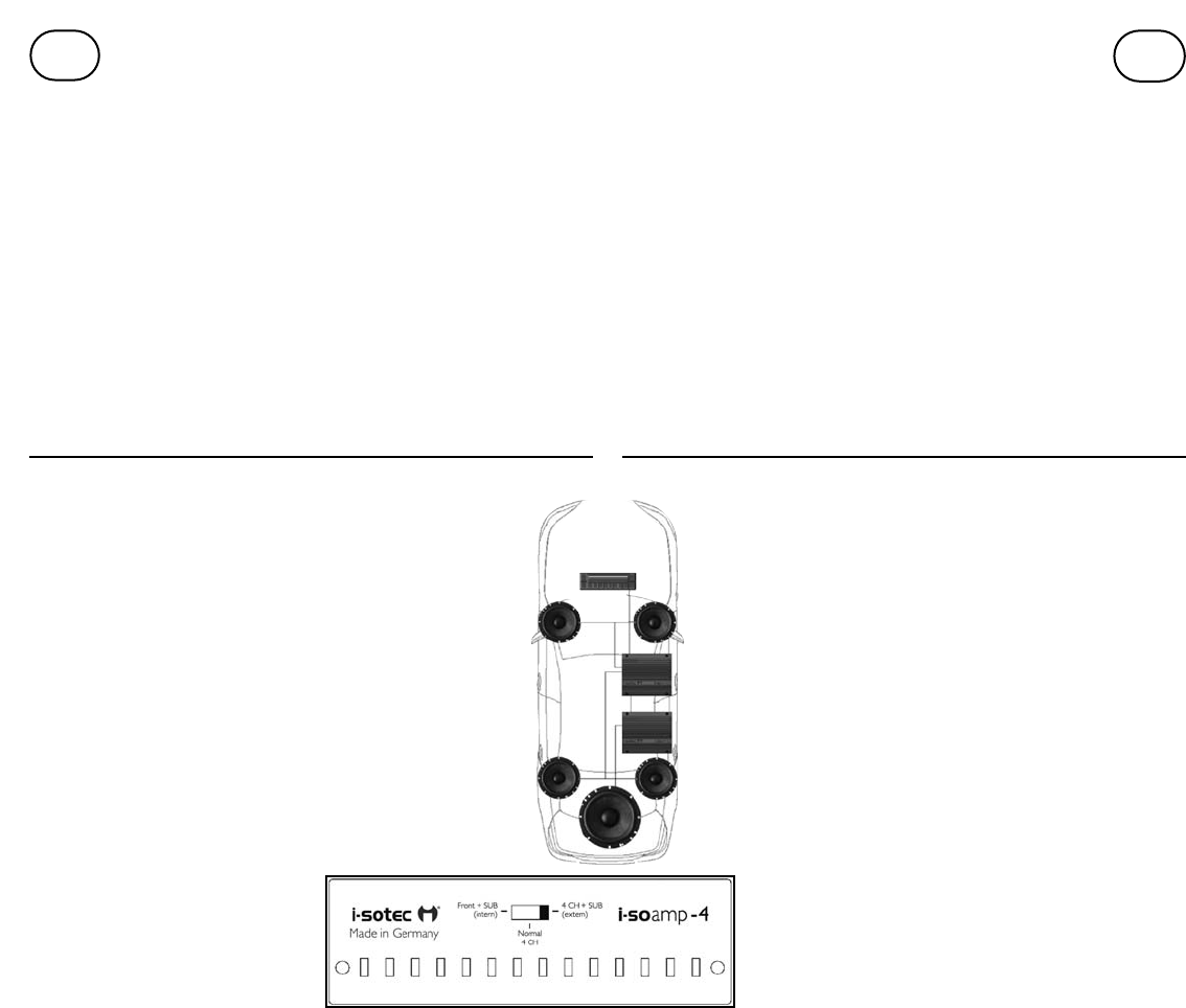
A.1.5 Four loudspeakers + Subwoofer (i-soamp-4/4cx)
With this connection option, the front and rear loudspeakers are
driven by the i-soamp while the bass loudspeaker is driven by an
additional i-soamp-2 two-channel-amplifier. Signal distribution for
the amplifiers is performed via a separate split-adaptor AD-0124
available from i-sotec.
Use only original i-sotec subwoofers! Other loudspeakers can dama-
ge the i-soamp!
Due to the increased power demand for these two amplifiers it is
important to connect the amplifiers directly to the battery. See
Chapter A.1.7 for additional information.
With this connection option, the selector switch for the i-soamp-4
or -4cx is set to the "4CH+Sub" position. In this switch position the
active filters required for the front and rear loudspeakers are auto-
matically activated.
The two amplifiers have a max. current requirement of 15A per
amplifier. In a few vehicles and when connecting to two amplifiers,
the radio wiring cannot cover this power requirement.
The i-soamps must then be connected directly to the battery.
(See Chapter A.1.7)
The wiring diagram is the same as described in Chapter
A.1.2. Instead of the car radio ISO loudspeaker receptacle,
however, now the free ISO loudspeaker receptacle of the
split-adaptor AD-0124 is to be used to connect the cable
harness of the i-soamp-2 to the car radio. For more details
on connecting the i-soamp-2, see chapter A1.5A.
Pegeleinstellung für die vorderen Lautsprecher erfolgt über den
Regler Level Front. Der Subwoofer wird über den Regler Level Rear
geregelt.
Nachdem der Kabelbaum des i-soamp mit dem Kompaktstecker am i-
soamp angeschlossen ist, werden die Lautsprecher folgendermaßen ange-
schlossen:
1. ISO-Lautsprecherstecker des Fahrzeugkabelbaums (vom Radio trennen) mit
ISO-Lautsprecherkupplung (braun) des i-soamp-Kabelbaums verbinden.
2. Die Verbindungen der 4-poligen Stecker lösen und dann, wie auf der
Abbildung zu sehen, miteinander verbinden. Es werden dabei die beiden 4-
poligen Stecker, die sich an der ISO-Lautsprecherkupplung und an dem ISO-
Lautsprecherstecker befinden, miteinander verbunden.
3. Den Subwoofer mit dem zugehörigen Anschlusskabel am passenden
Stecker des i-soamp-Kabelbaums anschließen.
4. Die ISO-Lautsprecherkupplung des i-soamp-Kabelbaums mit der ISO-
Lautsprecherkupplung des Autoradios verbinden.
5. Stromanschluss: Siehe Kapitel A.1.6 bzw. A.1.7.
A1.5 Anschlussvariante „Vier Lautsprecher und Subwoofer”
(i-soamp-4/4cx)
Bei dieser Variante werden die vorderen Lautsprecher und die hinte-
ren Lautsprecher mit dem i-soamp angetrieben. Der Basslautsprecher
wird mit einem optionalen i-soamp-2 angetrieben. Die
Signalverteilung für die Verstärker erfolgt über den separat erhältli-
chen Y-Adapter AD-0124 von i-sotec. Verwenden Sie ausschließlich
Original Subwoofer von i-sotec! Andere Lautsprecher können den
i-soamp beschädigen!
Durch den erhöhten Strombedarf der beiden Verstärker ist es wich-
tig, dass sie direkt an die Batterie angeschlossen werden. Weitere
Informationen hierzu siehe Kapitel A.1.7
Der Wahlschalter des i-soamp wird bei dieser Anschlussvariante auf
die Position „4CH+Sub“ gestellt. In dieser Schalterposition werden
die benötigten aktiven Filter für die vorderen und hinteren
Lautsprecher automatisch aktiviert.
Der Lautsprecheranschussplan für den i-soamp entspricht dem
Anschlussplan in Kapitel A.1.3 (Lautsprecher-Anschlussvariante
„Normal“). Die Einstellung für den
Wahlschalter des i-soamp-2 und den
Lautsprecheranschlussplan sowie
Hinweise zur Verwendung des Y-
Adapters AD-0124 entnehmen Sie bitte
der Bedienungsanleitung des i-soamp-2
in Kapitel A1.5A
D
UK
 Manymanuals.com
 Manymanuals.de
 Manymanuals.fr
 Manymanuals.it
 Manymanuals.pl
 Manymanuals.cz
 Manymanuals.es
 Manymanuals-pt.com
Kommentare zu diesen Handbüchern