Braun Corporation FMVSS No. 403 Quick Reference Installation Sheet 34274 Rev. A
2
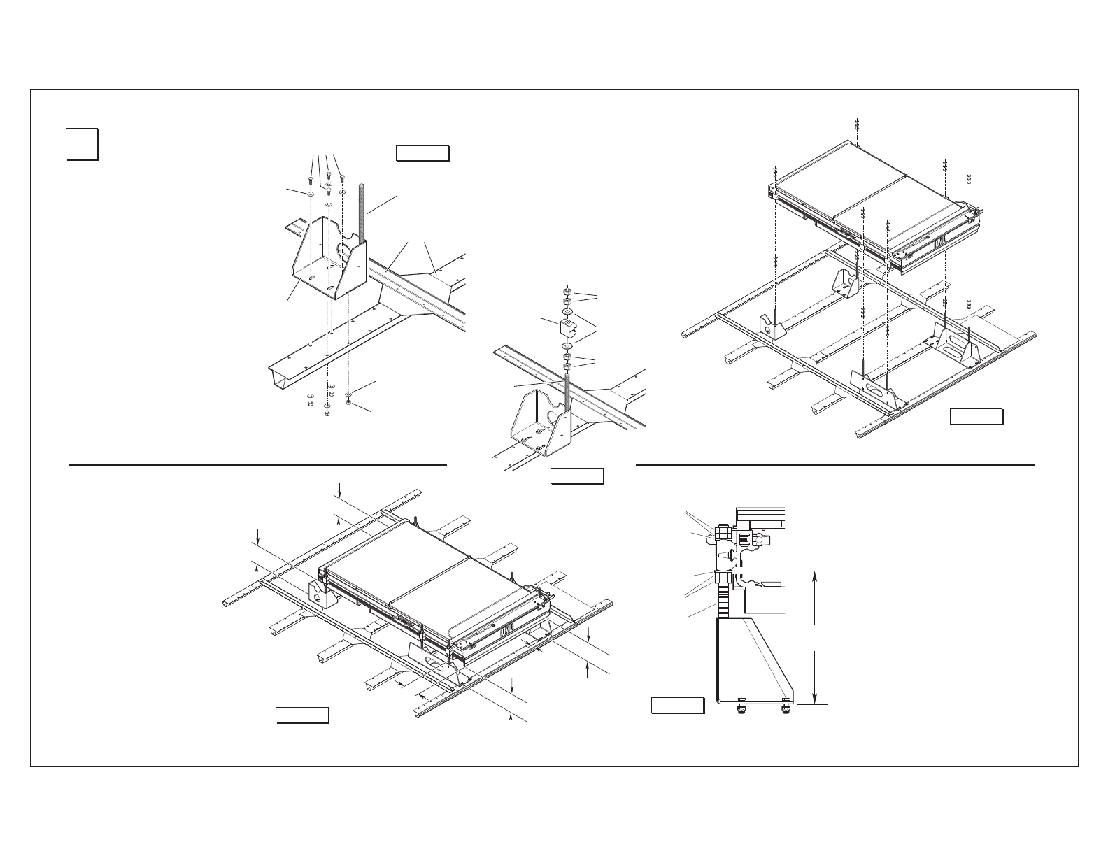
Secure Lift
1. Attach Mounting Brackets to
Vehicle Framing Members
Position lift mounting brackets as
detailed in Step 1 (see Figures C, D
and F). Oval slotted mounting holes
are provided in the mounting brackets
to allow adjustment. Carefully drill
21/64" (.328") diameter mounting
holes at the center of the oval mount-
ing slots (holes may be present).
Twenty 5-16-18 x 1" hex bolts are
supplied for bolting the lift mounting
brackets to the vehicle framing mem-
ber (four per inboard bracket and six
per outboard bracket).
Place a flat washer onto each mount-
ing bolt. Insert bolts through mount-
ing bracket, vehicle floor and fram-
ing member as shown in Figure D.
Installation is typical for all brackets
(outboard brackets require 6 mount-
ing bolts each).
All fasteners must meet FMVSS
571.403 Section 6.3.
2. Position and secure lift.
Thread two 3/4" hex jam nuts fully onto each mounting
bracket all-thread stud. Place one large diameter flat
washer onto each all-thread stud. See Figures G and H.
Carefully position lift in vehicle (aligned with mounting
brackets). Position (slide) the six lift mounting clamps
along the sides of the lift housing until aligned with
mounting bracket all-thread studs. See Figure F. Lower
lift onto mounting bracket studs
3. Height Adjustment
The lift outer barrier must be aligned
with
the vehicle access hole.
The lift housing must be aligned
with vehicle chassis (level). Adjust
the 3/4" hex jam nuts on the all-
thread mounting studs at all 4 corners
of the lift until dimensions A, B, C
and D are equal (within 1/16"). See
Figure G.
Place one large diameter flat washer
onto each mounting bracket all-
thread stud. Thread two 3/4" hex jam
nuts fully onto each all-thread stud
(against lift mounting clamp).
In-Out Positioning
Position the lift to achieve a 2” over-
lap between the deployed inboard
barrier and the vehicle floor.
Figure F
4. Horizontial Adjustment
Shift lift and mounting brackets left-to-right as
needed (lift must be centered in door opening).
Tighten the 5/16" bolts securing mounting
brackets (shown in Figure D) to the frame.
Torque Specifications: 20 foot pounds.
Tighten upper set of 3/4" hex jam nuts (with
flat washer) down to the lift mounting clamps.
Tighten jam nuts.
Torque Specications: 100 to 120 foot pounds.
Shipping Block Removal:
Wood blocks are placed in the lift housing to
prevent lift damage during shipment. Remove
shipping blocks from platform and carriage
before running (activating) lift. Refer to Ship-
ping Block Removal Instruction 28942.
Figure E
Figure H
Figure G
Dimensions A, B, C and D
must be equal (within 1/16
").
Vehicle
Framing
Members
5/16-18 x 1"
Hex Bolt
Flat
Washer
(typical)
Nylock Hex Nut
(typical)
All-Thread
Stud
Figure D
Lock Washer
(typical)
Inboard
Mounting
Bracket
Flat Washer
Jam Nuts
Lift Clamp
Jam Nuts
All-Thread
Stud
10¼”
Lift Housing
Mounting
Bracket
Jam Nuts
Flat Washer
Lift Clamp
Flat Washer
Jam Nuts
All-Thread
Mounting
Stud
A
D
B
C
2-1/2
"
5-3/8
"
 Manymanuals.com
 Manymanuals.de
 Manymanuals.fr
 Manymanuals.it
 Manymanuals.pl
 Manymanuals.cz
 Manymanuals.es
 Manymanuals-pt.com
Kommentare zu diesen Handbüchern