Braun Corporation FMVSS No. 403 Quick Reference Installation Sheet 32494
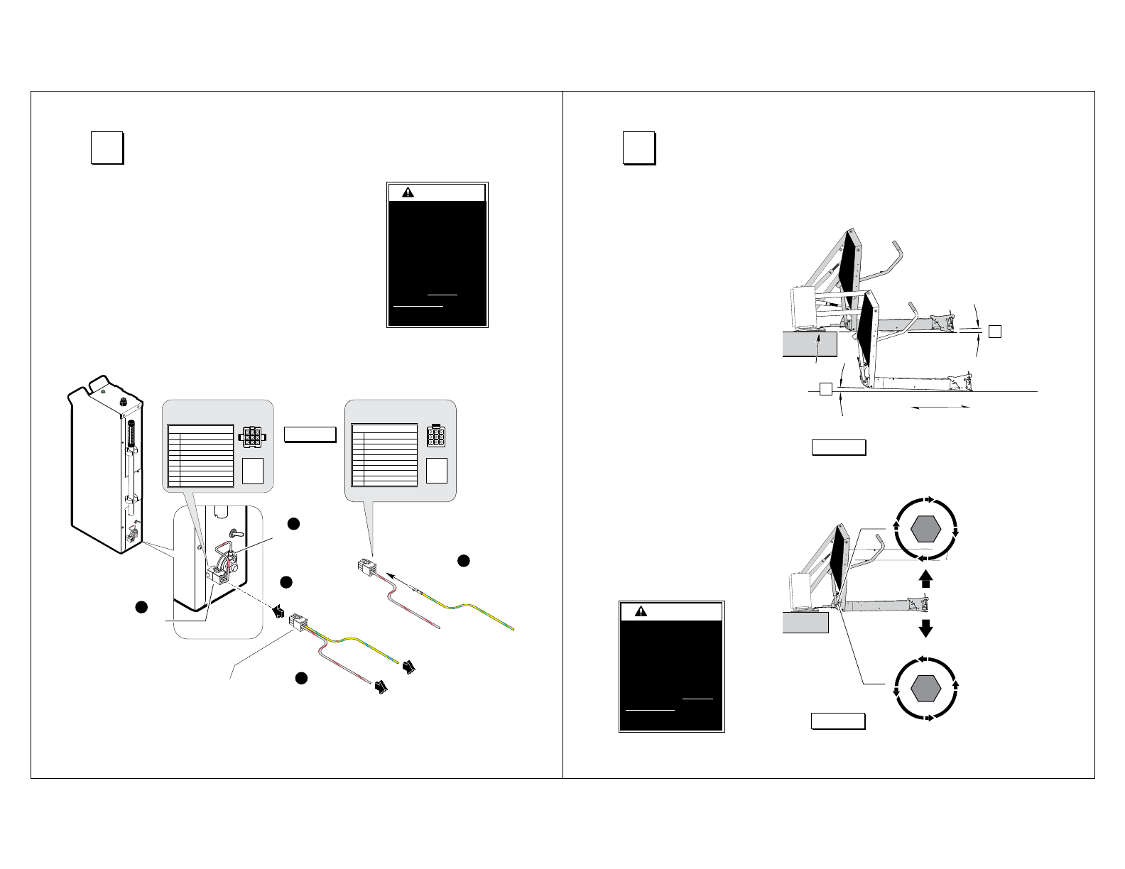
Vehicle and Lift Interlocks
The pump module is equipped
with a lift interface 9-circuit con-
nector (female socket). A mating
9-circuit connector (male plug) is
supplied.
To meet minimum NHTSA
requirements, connect to vehicle
interlock harness as outlined
below (Steps 1-5)
Optional Interlock Kits
Universal Interlock Kit 30940K is
available for easy interface with
vehicle OEM electronic signals.
Instrument Panel Display Kit
30938K provides an LED
Panel Display that interfaces
with Braun Universal Interlock Kit
30940K.
Detailed installation instructions
are supplied with interlock kits.
Note: All Braun Corporation in-
terlocks require a positive (+12V)
Lift Stowed signal (Pin 7).
INTERLOCK
CONNECTOR - P21
6
5
4
3
2
1
SIGNAL DEFINITION NO.
9-COND WIRE CODE
7
8
9
VEHICLE SECURE (INPUT)
NOT USED
NOT USED
NOT USED
NOT USED
NOT USED
LIFT STOWED (+12V)
NOT USED
LIFT STOWED (GND)
46 5
13 2
79 8
1
3
2
4
6
5
7
9 8
T
o Interlock
Disconnect
2
1
5
Disconnect
and remove
eye terminal
Lift
Pump
Module
Connect
4
Connect vehicle
interlock signal wires
3
Install 31798A
in cavity 7 (+) or 9 (-)
Shipped
As
VEHICLE SECURE
SIGNAL
(Grey/Red)
LIFT S
T
OWED
SIGNAL
(
Yellow/Light Blue)
PUMP MODULE
CONNECTOR - J21
6
5
4
3
2
1
SIGNAL DEFINITION NO.
9-COND WIRE CODE
7
VEHICLE SECURE (INPUT)
NOT USED
NOT USED
NOT USED
NOT USED
NOT USED
LIFT STOWED (+12V)
64 5
31 2
97 8
3
1
2
6
4
5
9
7
8
8
NOT USED
LIFT STOWED (GND)
9
Manufacturer’s Part Numbers
Connector: AMP 172169
Terminal:TYCO 770904-3
Figure H
Note: Pins 7 and 9
300mA maximum.
4
Connect Interlocks
Install and verify
proper operation of
all NHTSA mandated
interlocks as
specified. Failure
to do so will result
in a non-compliant
installation and may
result in serious
bodily injury and/or
property damage.
Adjust Platform Angle
Inboard
Outboard
Wedges
Angle A
equals
Angle B.
✓
B
Figure I
Adjustments to platform
angle may be required
if base plate wedges
are used. See Figures I
and J.
Floor Level Positioning:
Reset floor level positioning
if wedges are used. See
Floor Level Adjustment
panel.
L
O
O
S
E
N
T
I
G
H
T
E
N
Turn
counterclockwise
to
lower
outboard end
of platform
Turn
clockwise
to
raise
outboard end
of platform
Figure J
A
Approximately
1” Clearance
Reset floor level
position as specified
in Floor Level
Adjustment Instruc-
tions if wedges are
used. Failure to do so
may result in serious
bodily injury and/or
property damage.
5
 (8 Seiten)
 Manymanuals.com
 Manymanuals.de
 Manymanuals.fr
 Manymanuals.it
 Manymanuals.pl
 Manymanuals.cz
 Manymanuals.es
 Manymanuals-pt.com
Kommentare zu diesen Handbüchern