Braun Corporation FMVSS No. 403 Quick Reference Installation Sheet 32553 Rev. A
VEHICLE
BO
X FRAME
VEHICLE
CHASSI
S MEMBER
2
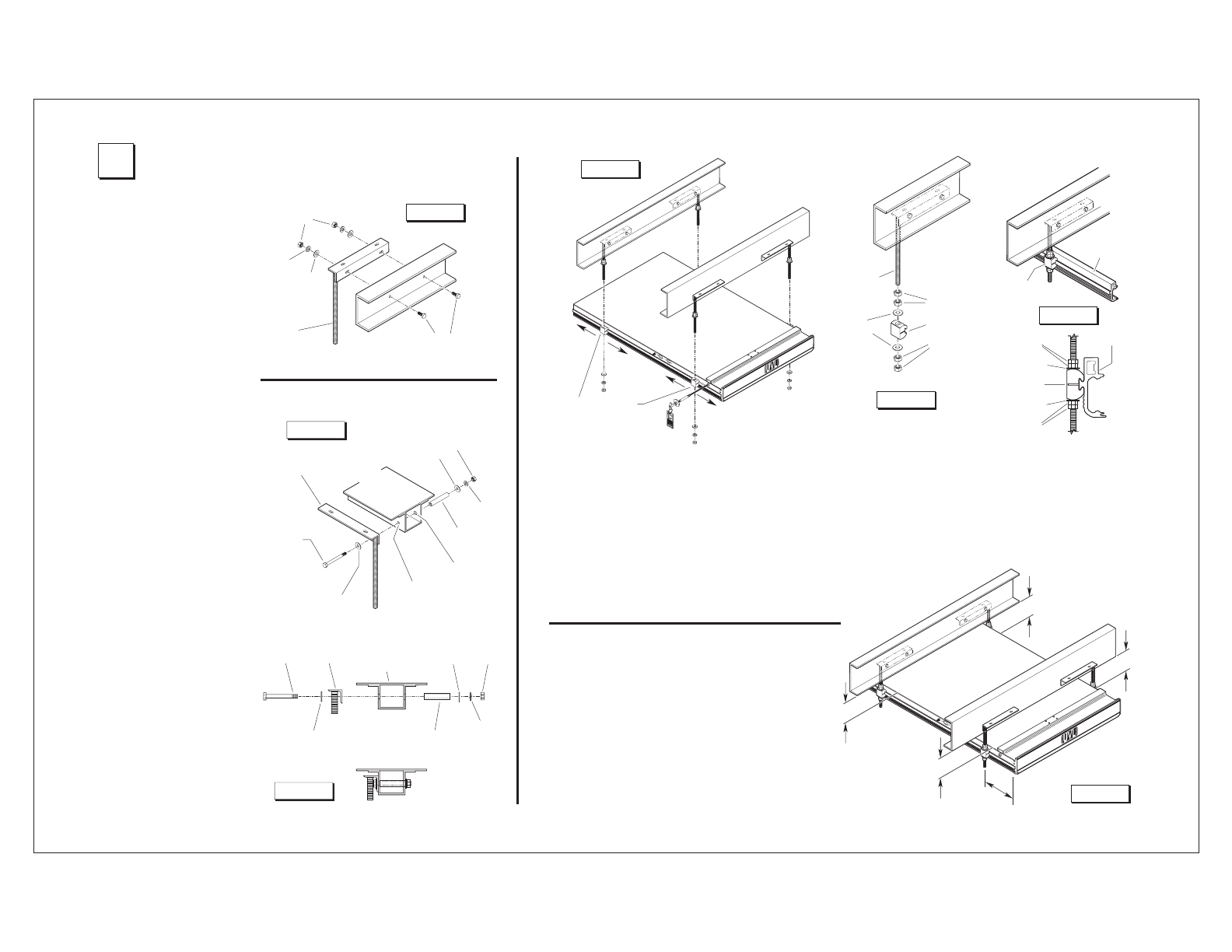
Secure Lift
Attach Mounting Brackets to
Vehicle Frame
Mounting bolts must be routed
horizontally through the verti-
cal face of the “L” brackets and
framing members as shown in
Figures D, E and F.
Eight 3/8-16 x 1-1/2" hex bolts
are supplied for bolting the all-
thread mounting brackets to the
frame (two per bracket). Oval
slotted mounting holes are pro-
vided in the mounting brackets
to allow adjustment. Carefully
drill 25/64" (.390") diameter
mounting holes at the center of
the oval mounting slots.
Channel Frame Applications:
Secure mounting bolts as speci-
fied in Figure D.
Box Frame Spacers: Position
tubing spacers as shown at
right to prevent collapsing the
box frame. Carefully drill a
25/64" (.390") diameter mount-
ing hole through one side of the
box frame. Drill a 5/8" (.625")
diameter hole through the
opposite side of box frame to
allow installation of spacer. Cut
spacer tubing to length (equal
to thickness of box frame).
Note: A longer 3/8-16 bolt will
be required for box frame appli-
cations. Secure mounting bolts
as specified in Figures E and F.
All fasteners must meet FM-
VSS 571.403 Section 6.3.
“Box” Framing Member
“Channel” Framing Member
3/8-16 x 1-1/2"
Hex Bolt
All-Thread
Bracket
Box
Framing
Member
Spacer
Flat
Washer
Lock
Washer
Hex
Nut
Flat Washer
3/8-16
Hex Bolt
3/8-16 x 1-1/2"
Hex Bolt
Flat
Washer
Lock
Washer
Hex
Nut
All-Thread
Bracket
Spacer
Flat
Washer
Lock
Washer
Hex
Nut
All-Thread
Bracket
Flat Washer
Figure D
Figure E
5/8"
Diameter
Hole
25/64"
Diameter
Hole
“Box” Framing Member
Figure F
Assembled
Spacer Tubing
Length: Equal
to thickness of
box frame.
Shipping Block Removal:
Wood blocks are placed in the
lift housing to prevent lift dam-
age during shipment. Remove
shipping blocks from platform
and carriage before running
(activating) lift. Refer to
Shipping Block Removal
Instruction 28942.
W
A
R
N
I
N
G
8
1
8
2
3
P
u
sh
T-
h
and
l
e
i
n
f
u
l
l
y
and
m
a
n
u
a
l
l
y
m
o
v
e
p
l
a
t
f
o
rm
i
n
a
n
d
o
u
t
t
o
en
g
a
g
e
pl
a
t
fo
r
m
l
o
ck
b
e
f
o
r
e
d
r
i
v
i
ng
v
eh
i
c
l
e
.
F
ai
l
u
r
e
t
o
l
o
ck
p
l
a
t
f
o
rm
m
a
y
r
es
u
l
t
i
n
u
n
i
n
t
e
n
d
ed
p
l
a
t
f
o
rm
d
ep
l
o
y
men
t
.
U
n
i
n
te
n
d
ed
p
l
a
t
f
o
r
m
d
e
p
l
o
y
m
ent
m
a
y
r
e
sul
t
i
n
s
e
ri
o
u
s
b
o
d
i
l
y
i
nj
u
r
y
a
n
d
/
o
r
p
r
o
per
t
y
da
m
a
g
e
.
D
o
n
o
t
r
e
m
ov
e
!
VEHI
CLE
CHASSIS MEMB
ER
VEHI
CLE
CHASSI
S MEMB
ER
Align mounting clamps
with all-thread studs.
Position and secure lift.
Thread two 3/4" hex jam nuts fully
onto each mounting bracket all-thread
stud. Place one large diameter flat
washer onto each all-thread stud (use
tape to hold in place). See Figures G
and H.
Carefully position lift under vehicle
(aligned with mounting brackets).
Position (slide) the four lift mounting
clamps along the sides of the lift hous-
ing until aligned with mounting bracket
all-thread studs. See Figure G.
Height Adjustment
The lift housing must be
aligned with vehicle chas-
sis. Adjust the 3/4" hex jam
nuts on the all-thread mount-
ing studs at all 4 corners of
the lift until dimensions A, B, C
and D are equal (within 1/16").
See Figure J.
In-Out Positioning
Position the lift to achieve a 2”
overlap between the deployed
inboard barrier and the vehicle
floor.
Figure G
Jam Nuts
Lift Clamp
Jam Nuts
All-Thread
Stud
Flat
Washer
Jam Nuts
Flat Washer
Lift Clamp
Flat Washer
Jam Nuts
Lift
Housing
Lift
Housing
Lift
Clamp
Shift lift and mounting brackets
left-to-right as needed (lift must
be centered in door opening).
Tighten the 3/8" bolts securing
mounting brackets to the frame.
Torque Specifications: 25 to 30
foot pounds.
Figure H
Figure I
Figure J
Note: The two outboard mounting
brackets should be positioned a
maximum of 16” from the end of the
cassette. See Figure J.
Carefully raise lift into position as high
as possible (height adjustment outlined
below). Place one large diameter flat
washer onto each mounting bracket all-
thread stud. Thread two 3/4" hex jam
nuts fully onto each all-thread stud (up
against lift mounting clamp).
VEHI
CLE
CHASSIS MEMB
ER
VEHICLE
CHASSIS MEMBER
A
B
C
D
16”
Max
imum
Dimensions
A, B, C and D
must be equal
(within 1/16
").
Tighten upper set of 3/4" hex
jam nuts (with flat washer)
down to the lift mounting
clamps. Tighten jam nuts.
Torque Specifications: 100
to 120 foot pounds.
 (6 Seiten)


 (95 Seiten)
 (19 Seiten)
 (41 Seiten)
 Manymanuals.com
 Manymanuals.de
 Manymanuals.fr
 Manymanuals.it
 Manymanuals.pl
 Manymanuals.cz
 Manymanuals.es
 Manymanuals-pt.com
Kommentare zu diesen Handbüchern